Updated P&ID Requirements
The revised P&ID touched multiple areas of the system at once, so integrating it meant cross-checking process requirements against equipment positions and piping — not patching one section in isolation.
Pressure Regulating System Design Optimization
A 1500 Sm³/h PRS that already had a working design — until a P&ID and process flow revision changed the brief midway through. The job wasn't to start over; it was to fold new instrumentation and piping requirements into an existing 3D model without losing the compact, accessible, fabrication-ready layout the original already had.
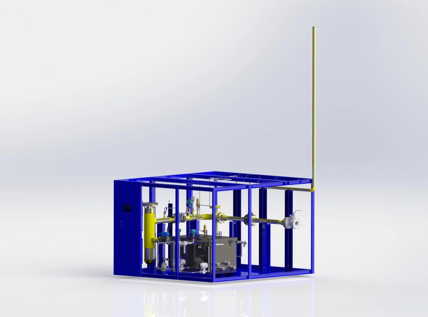
Engineering designs rarely stay frozen at the first version. As a project moves forward, process requirements get refined, stakeholders ask for changes, and the documentation evolves to match. That's exactly what happened here: a revised P&ID and process flow diagram introduced new instrumentation and altered piping requirements for a PRS that was already sized at 1500 Sm³/h.
The scope of work wasn't a cosmetic update to the 3D model. It meant re-reading the new process documentation in full, working out exactly what it changed, and rebuilding the affected parts of the layout so the physical skid matched the paper design again — without letting the enclosure grow or the system become harder to maintain.
The engineering objective stayed simple even as the work got more involved: match the latest P&ID, fit the new components in, and hand over a system that's still compact, safe, and practical to build.
Four things shifted at once, and each one had knock-on effects on the others.
The revised P&ID touched multiple areas of the system at once, so integrating it meant cross-checking process requirements against equipment positions and piping — not patching one section in isolation.
New instruments needed a home in a layout that wasn't drawn with them in mind, which meant re-evaluating spacing throughout rather than just slotting them into a gap.
The enclosure footprint stayed fixed. Every component that needed to come in had to be justified against the access clearance it would cost somewhere else.
Several routes had to change to match the new configuration, and the goal was a clean path that didn't introduce avoidable bends or congestion just to make room.
Rather than chasing each change as it came up, the redesign followed a deliberate sequence so nothing got fixed twice.
Before touching the model, the revised documentation was read end to end to map out every change and where it would land in the physical layout.
Equipment placement was reassessed as a whole — not component by component — to land on an arrangement that reduced interference instead of just absorbing the new parts.
Routes were redrawn together with the new equipment positions, aiming for paths that stayed simple to fabricate and didn't create unnecessary congestion.
Every change was checked back against the approved P&ID to confirm the 3D model and the process documentation were saying the same thing.
Reworking a layout under a revision is a different problem than designing one from scratch — every decision has to justify itself against the version that already existed.
Bolting new instrumentation onto the existing arrangement would have worked in the short term, but it would have eaten into clearances and made the system harder to read and service. Restructuring the layout kept the equipment arrangement logical instead of letting it accumulate patches.
Maintenance activity is what actually determines whether a PRS stays reliable over its life. Components were positioned so inspection, troubleshooting, and replacement don't require dismantling neighboring equipment, even with the added instrumentation density.
Efficient routing isn't about appearance — a cleaner path is also a simpler one to fabricate, fit, and inspect. Optimizing the routes alongside the layout changes kept installation complexity from creeping up with every added requirement.
Every layout option was weighed against what the workshop could actually build without special tooling or rework once it left the design stage. Fabrication practicality and cost efficiency were treated as design inputs, not a final check at the end.
Full compliance with the latest P&ID revision.
A cleaner, more logical equipment organization.
Simplified piping arrangement with fewer congestion points.
Better accessibility for routine maintenance activities.
A more straightforward path to fabrication and assembly.
A modular, field-ready PRS configuration within the original footprint.
The revised system absorbed every documented change while staying within its original compact footprint — proof that a tighter design and an updated one aren't mutually exclusive.
Treating a P&ID change as an opportunity to tidy the layout produced a better design than a literal patch would have.
Process requirements, fabrication constraints, and maintenance access all pull in different directions — the layout has to satisfy all three together.
Adding even a couple of instruments can force a rethink of piping and equipment arrangement well beyond their immediate footprint.
A logically arranged layout tends to fabricate and install more easily — clarity in the model translates into fewer surprises in the workshop.
The updated 3D model below. Additional renders, P&ID comparison views, and fabrication
photos will be added here as the project documentation comes in — drop matching files into
assets/img/projects/ to fill these slots.
Practical support for piping and process design, pressure reducing stations, gas train skids, CNG and hydrogen systems, mechanical design, technical documentation, and design review.